-40%
S.T.E.M. Arduino Nano 8 bit Shift Register Computer Bread Board STEM Kit 97 pcs
$ 12.13
- Description
- Size Guide
Description
S.T.E.M. Arduino Nano Shift Register Kit Computer Science E Learning All in One Kit. US Shipping.Start building a bread board computer. Learn about shift registers and how to control multiple L.E.D's with the Arduino Nano. Great for Elearning STEM classes with this 97 piece kit.. Students learn parallel and serial data input / output methods with the Arduino Nano. Kits are hand assembled in America and from the USA shipping.
Note: some pictures show a Arduino Uno. Kit contains an Arduino Nano with the same pin out.
Links to Arduino code and tutorials will be messaged upon purchase.
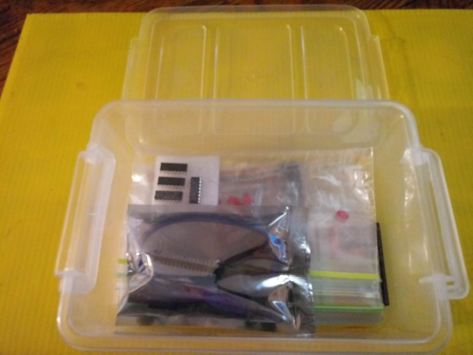
Kit Contains:
Arduino Nano - with soldered pins
USB cable
MB-102 840 point Bread Board
x2 74HC165 PISO 8 bit Shift Registers
x2 74HC595 SIPO 8 bit Shift Registers
x10 Push Buttons
x20 red LED's
x20 390 Ohm Resisters
x40 Dupont Style M to M Wires
Sturdy Plastic Storage Case
Example 1: One Shift Register
The first step is to extend your Arduino with one shift register.
The Circuit
1. Turning it on
Make the following connections:
GND (pin 8) to ground,
Vcc (pin 16) to 5V
OE (pin 13) to ground
MR (pin 10) to 5V
This set up makes all of the output pins active and addressable all the time. The one flaw of this set up is that you end up with the lights turning on to their last state or something arbitrary every time you first power up the circuit before the program starts to run. You can get around this by controlling the MR and OE pins from your Arduino board too, but this way will work and leave you with more open pins.
2. Connect to Arduino
DS (pin 14) to Ardunio DigitalPin 11 (blue wire)
SH_CP (pin 11) to to Ardunio DigitalPin 12 (yellow wire)
ST_CP (pin 12) to Ardunio DigitalPin 8 (green wire)
From now on those will be refered to as the dataPin, the clockPin and the latchPin respectively. Notice the 0.1"f capacitor on the latchPin, if you have some flicker when the latch pin pulses you can use a capacitor to even it out.
3. Add 8 LEDs.
In this case you should connect the cathode (short pin) of each LED to a common ground, and the anode (long pin) of each LED to its respective shift register output pin. Using the shift register to supply power like this is called
sourcing current.
Some shift registers can't source current, they can only do what is called
sinking current.
If you have one of those it means you will have to flip the direction of the LEDs, putting the anodes directly to power and the cathodes (ground pins) to the shift register outputs. You should check the your specific datasheet if you aren't using a 595 series chip. Don't forget to add a 470-ohm resistor in series to protect the LEDs from being overloaded.
Circuit Diagram
The Code
Here are three code examples. The first is just some "hello world" code that simply outputs a byte value from 0 to 255. The second program lights one LED at a time. The third cycles through an array.
595 Logic Table
595 Timing Diagram
The code is based on two pieces of information in the datasheet: the timing diagram and the logic table. The logic table is what tells you that basically everything important happens on an up beat. When the clockPin goes from low to high, the shift register reads the state of the data pin. As the data gets shifted in it is saved in an internal memory register. When the latchPin goes from low to high the sent data gets moved from the shift registers aforementioned memory register into the output pins, lighting the LEDs.
Code Sample 1.1 Hello World
Code Sample 1.2 One by One
Code Sample 1.3 Using an array
Example 2
In this example you'll add a second shift register, doubling the number of output pins you have while still using the same number of pins from the Arduino.
The Circuit
1. Add a second shift register.
Starting from the previous example, you should put a second shift register on the board. It should have the same leads to power and ground.
2. Connect the 2 registers.
Two of these connections simply extend the same clock and latch signal from the Arduino to the second shift register (yellow and green wires). The blue wire is going from the serial out pin (pin 9) of the first shift register to the serial data input (pin 14) of the second register.
3. Add a second set of LEDs.
In this case I added green ones so when reading the code it is clear which byte is going to which set of LEDs


